Building the Mini12 #
Update: This project was my first try at building an amplifier, because of this it is pretty awful in terms of performance, it has very noticeable crossover distorsion. For better designs please look at newer posts here.
Last week, I decided to take on a very simple project: build a very low distortion, reasonably powerful, battery-powered amplifier that could fit in a very small, transparent enclosure that I had.
The main idea was to have this very small amplifier that could be moved around the house and powered from some 18650 cells so that I could enjoy some music with my friends when they come for our regular LAN parties. Usually we use one of those crappy iPod dock/speaker things that everyone loves, but, personally, they don't sound very good to me.
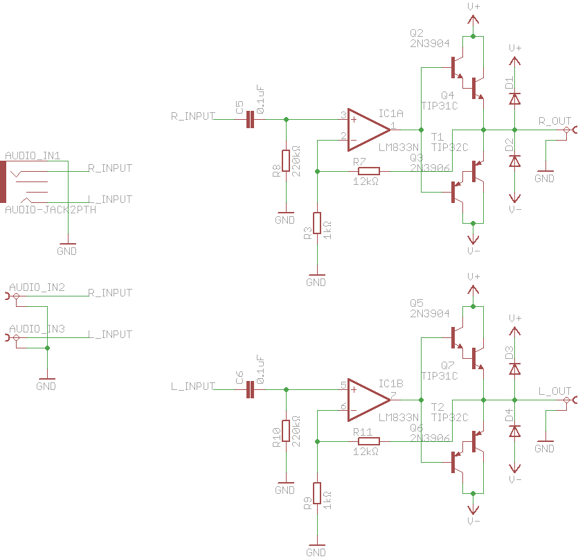
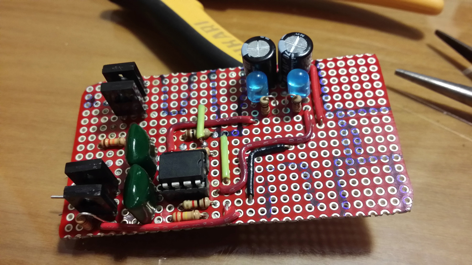
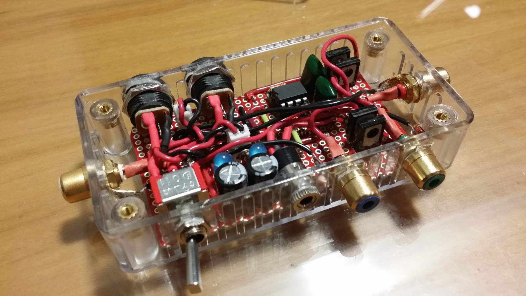
Since this was a quick project, I decided to make it as simple as possible to avoid any trouble. The easiest it could be was to use an audio op-amp driving a class B output made with darlington transistors with some negative feedback to keep the distortion really low, so that's what I did:
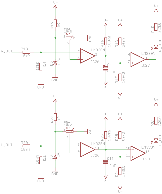
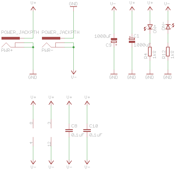
I also designed a very simple peak detector to detect any clipping on the output to make sure the signal was as clean as possible, but, sadly, my case was so small that I couldn't fit it in. Since it would be powered from 2 18650 packs (3 cells each) or a pair of 9V batteries, the power supply is extremely simplistic.
When all of the parts arrived, I decided to get everything prepared to be assembled the next day.
Choosing where to put the jacks and switches was a bit tricky since the space inside the enclosure was extremely small.
Since I wasn't patient enough to wait for a PCB, I decided to build the whole thing on a piece of protoboard which was a bit tricky because of the space the jacks took.
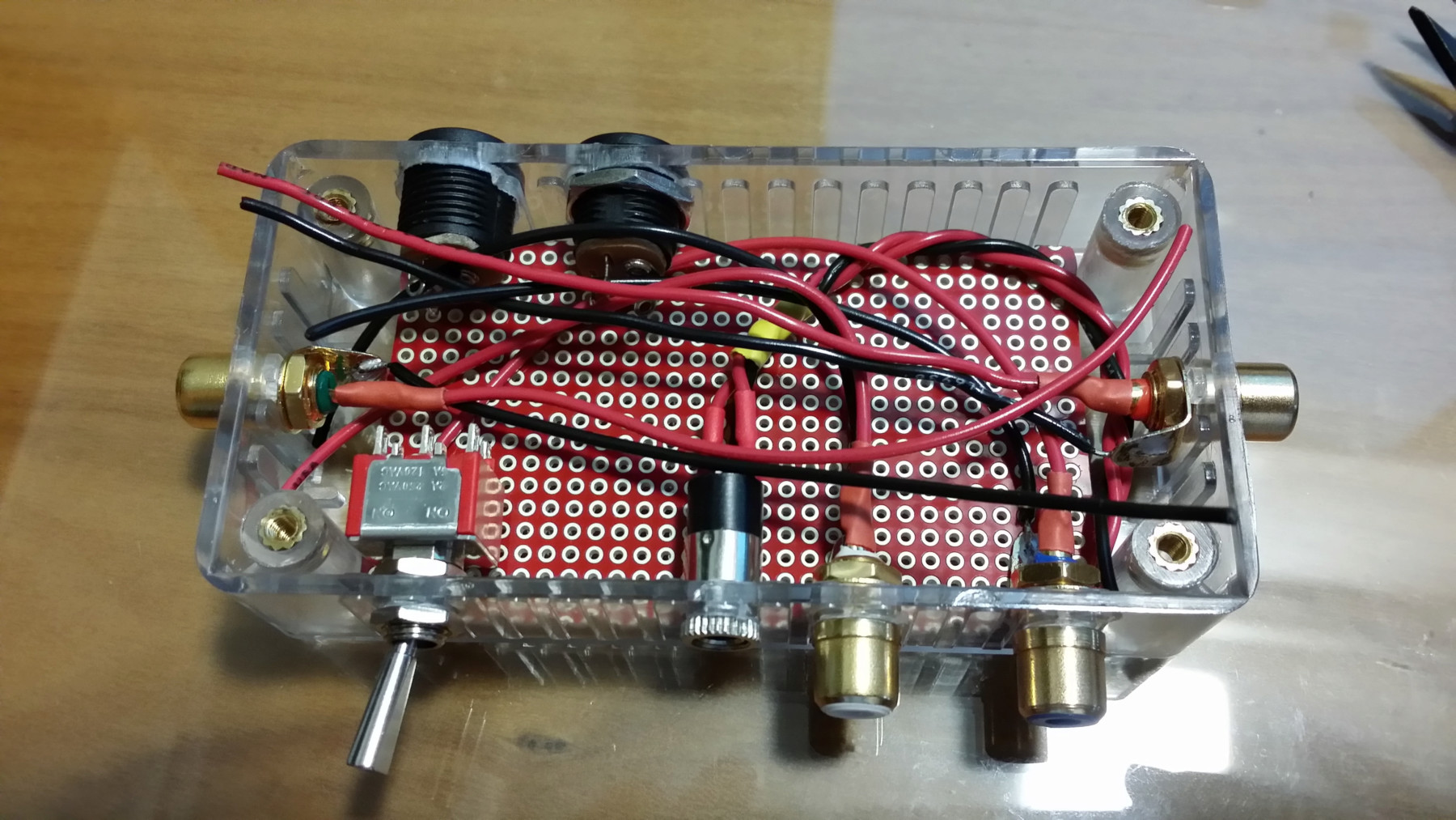
After soldering the headphone jack and on/off switch, mounted from the inside, it was time to solder the RCA jacks which had to be mounted from the outside. This was very difficult since I had to make the shortest cable possible while making sure that I could still lift the board up to solder the cable to the PCB.
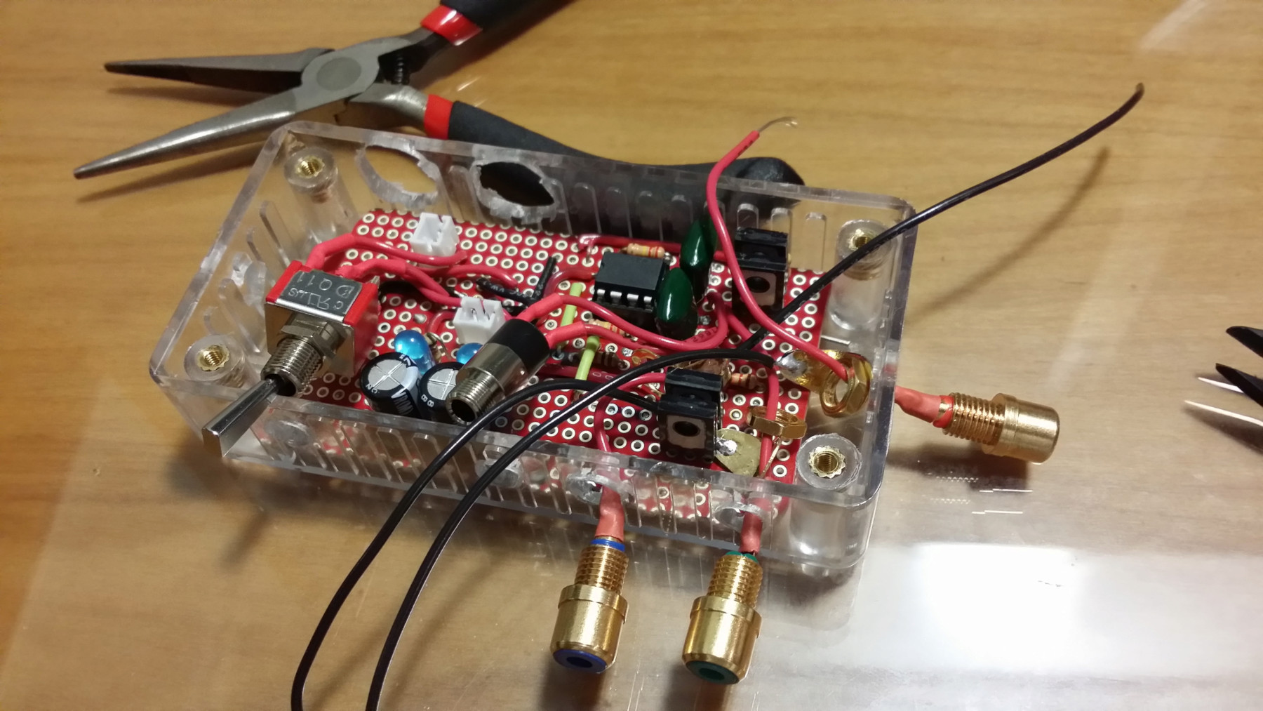
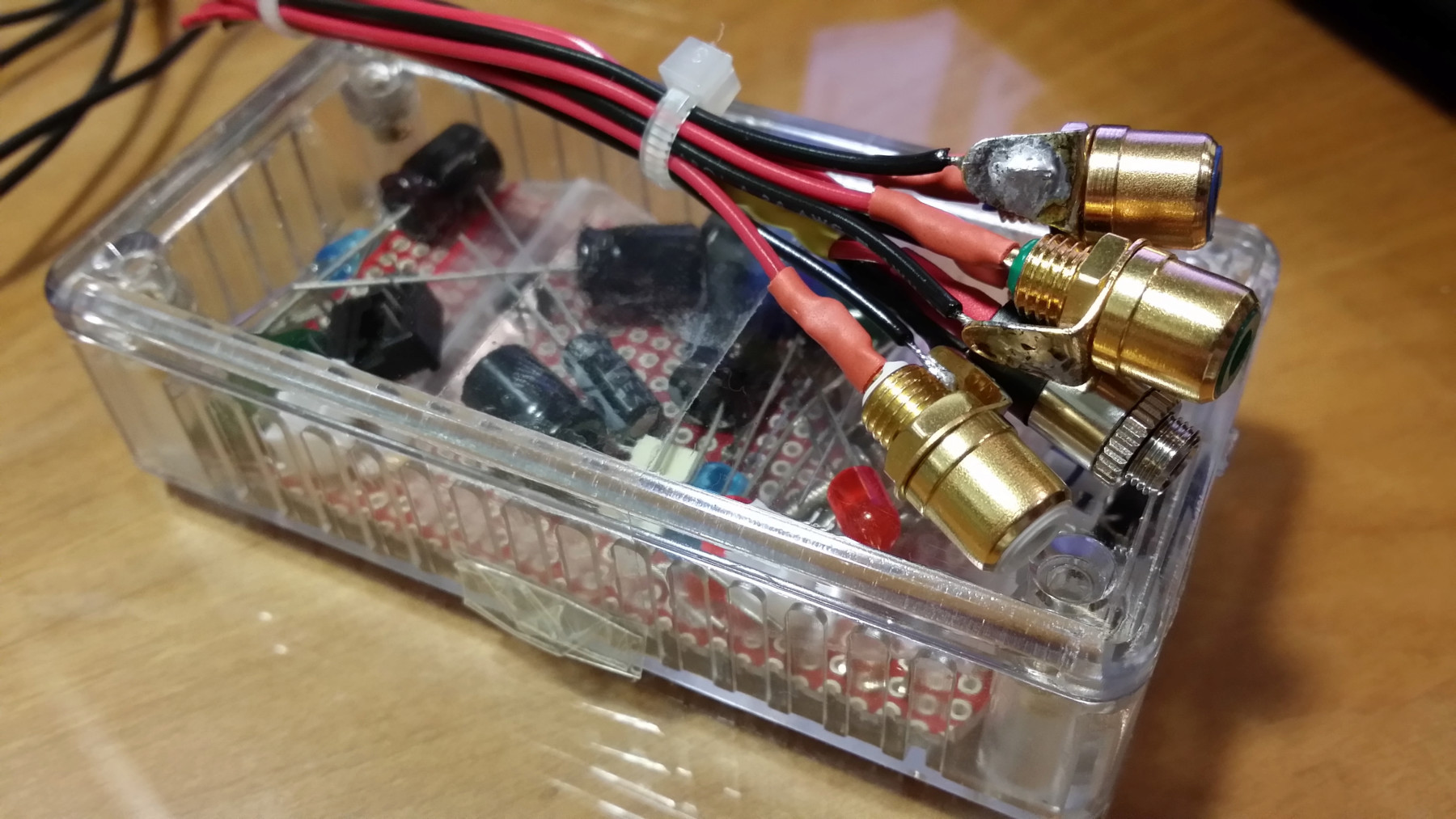
Sliding the board back into place was extremely difficult, but after a lot of wiggling, it was perfectly placed on the bottom of the enclosure, and I was ready to plug the power jacks into the JST connectors on the board. It was the only way to mount them, otherwise I wouldn't be able to lift the board to solder them.
Since it was 1:38AM, I was quite tired, and since I had been working on this thing for 7 hours and 12 minutes, I decided that it was time to sleep and leave the enclosure closing and testing for the next day. (Obligatory picture of the pile of wires and component leads)
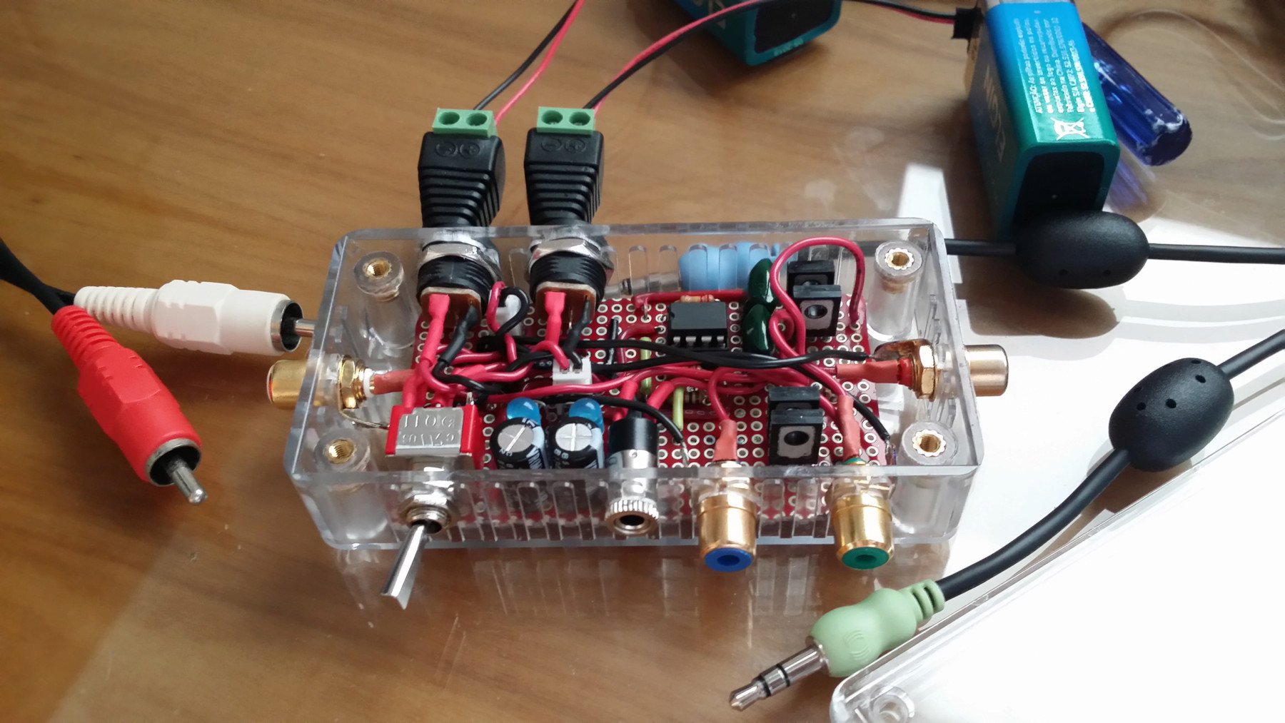
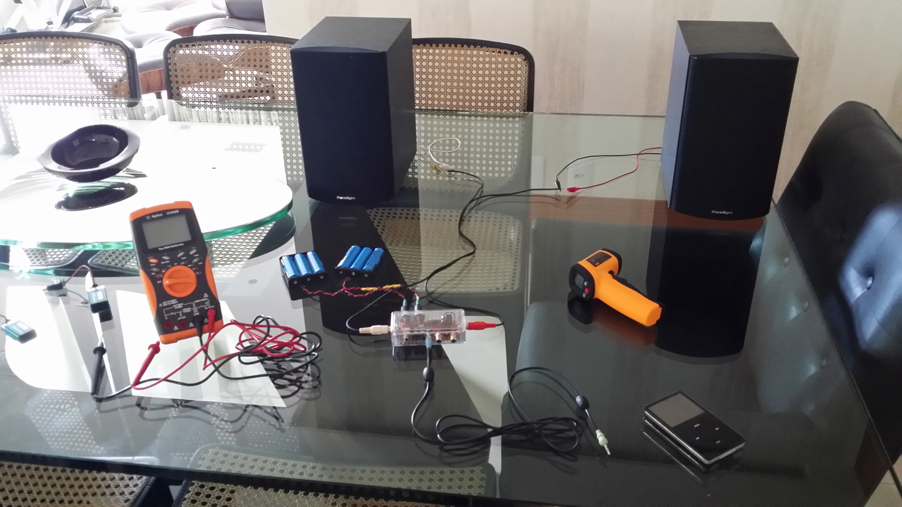
First thing to do in the morning was to test the little beast. This was the test setup (after using my oscilloscope and a dummy load to make sure everything was working fine). I had to use the living room table since my bench was a mess (as usual), and there was no space for the 2 speakers.
And that's all! If you want more technical information about the project, be sure to visit the GitHub repo. If you want to discuss it, jump on over to the diyAudio thread.
This article was imported from my old blog . Some things may be broken.